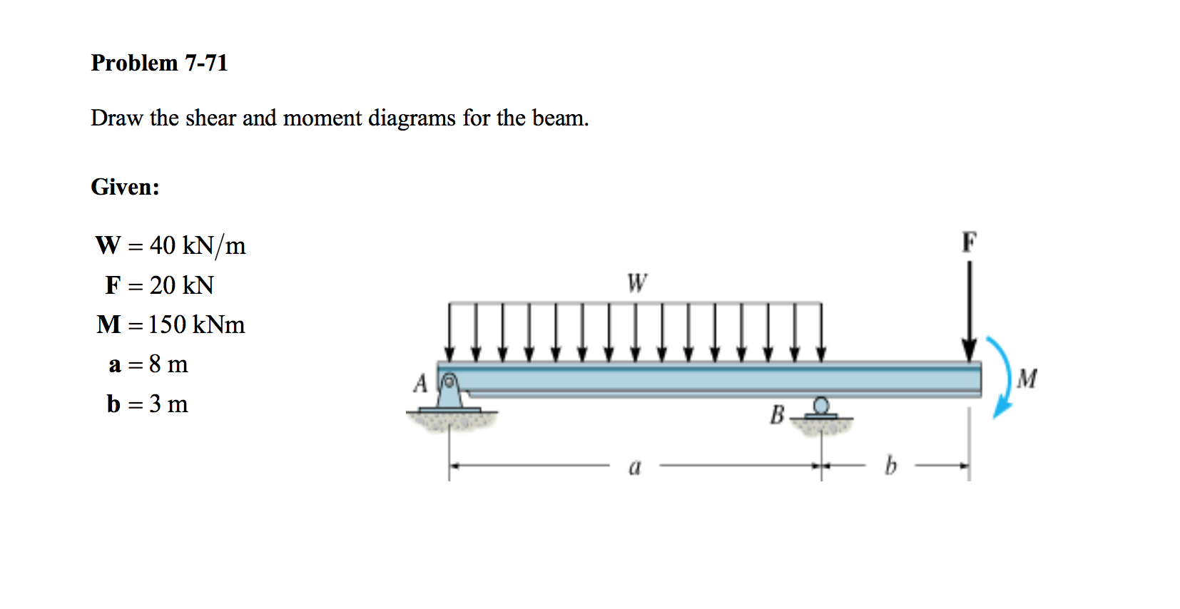
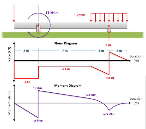
Draw The Shear And Moment Diagram For The Beam
Draw The Shear And Moment Diagram For The Beam - Φv f = ϕ * 0.62 * f uf * k r * k rd * (n n * a c + n x * a o). There is a long way and a quick way to do them. Web draw the shear force and bending moment diagrams for the cantilever beam supporting a concentrated load of 5 lb at the free end 3 ft from the wall. This page will walk you through what shear forces and bending moments are, why they are useful, the procedure for drawing the diagrams and some other keys aspects as well. Web calculate the reactions at the supports of a beam, frame and truss. In each problem, let x be the distance measured from left end of the beam. Web establish the m and x axes and plot the values of the moment at the ends of the beam. K rd is a reduction factor to account for reduced ductility of grade 10.9. Web figures 1 through 32 provide a series of shear and moment diagrams with accompanying formulas for design of beams under various static loading conditions. Web this video explains how to draw shear force diagram and bending moment diagram with easy steps for a simply supported beam loaded with a concentrated load. In each problem, let x be the distance measured from left end of the beam. K rd is a reduction factor to account for reduced ductility of grade 10.9. We go through breaking a beam into segments, and then we learn about the relationships between shear force. Φv f = ϕ * 0.62 * f uf * k r * k rd * (n n * a c + n x * a o). Web this video explains how to draw shear force diagram and bending moment diagram with easy steps for a simply supported beam loaded with a concentrated load. Shear and moment diagrams and formulas are excerpted from the western woods use book, 4th edition, and are provided herein as a courtesy of western wood products association. David roylance department of materials science and engineering massachusetts institute of technology cambridge, ma 02139 november 15, 2000. Web draw the shear force and bending moment diagrams for the cantilever beam supporting a concentrated load of 5 lb at the free end 3 ft from the wall. Web express the internal shear and moment in the cantilevered beam as a function of x and then draw the shear and moment diagrams. Divide the beam (of length l) into n segments. Web the first step in calculating these quantities and their spatial variation consists of constructing shear and bending moment diagrams, \(v(x)\) and \(m(x)\), which are the internal shearing forces and bending moments induced in. Skyciv beam tool guides users along a professional beam calculation workflow, culminating in the ability to view and determine if they comply with your region's design.. There is a long way and a quick way to do them. Shear and moment diagrams and formulas are excerpted from the western woods use book, 4th edition, and are provided herein as a courtesy of western wood products association. Web establish the m and x axes and plot the values of the moment at the ends of the beam.. Web draw the shear and moment diagrams for the beam 1) calculate the shear force and bending moment for the beam subjected to concentrated load as shown in the figure. Web our calculator generates the reactions, shear force diagrams (sfd), bending moment diagrams (bmd), deflection, and stress of a cantilever beam or simply supported beam. Web draw the shearing force. Web learn to draw shear force and moment diagrams using 2 methods, step by step. Divide the beam (of length l) into n segments. Web shear force and bending moment diagrams are powerful graphical methods that are used to analyze a beam under loading. David roylance department of materials science and engineering massachusetts institute of technology cambridge, ma 02139 november. Being able to draw shear force diagrams (sfd) and bending moment diagrams (bmd) is a critical skill for any student studying statics, mechanics of materials, or structural engineering. Web figures 1 through 32 provide a series of shear and moment diagrams with accompanying formulas for design of beams under various static loading conditions. Web express the internal shear and moment. You can continue reading through the solution below…or if you prefer video, you can watch me walk through the solution here. Web write shear and moment equations for the beams in the following problems. Also, draw the shear force diagram (sfd) and the bending moment diagram (bmd). Being able to draw shear force diagrams (sfd) and bending moment diagrams (bmd). Web shear and moment equations and diagrams for beams. Web the maximum positive and negative values on the shear and moment diagrams can be labeled based on the magnitudes of the shear force and bending moment at different locations along the beam. Web this is an example problem that will show you how to graphically draw a shear and moment. Shear and bending moment diagrams. Web draw the shear and moment diagrams for the beam 1) calculate the shear force and bending moment for the beam subjected to concentrated load as shown in the figure. Web our calculator generates the reactions, shear force diagrams (sfd), bending moment diagrams (bmd), deflection, and stress of a cantilever beam or simply supported beam.. Shear and bending moment equations. Web the maximum positive and negative values on the shear and moment diagrams can be labeled based on the magnitudes of the shear force and bending moment at different locations along the beam. To draw the shear and moment diagrams for the given overhang beam, one need to determine the reactions at the supports and. Web shear and moment equations and diagrams for beams. Web shear and moment diagrams are graphs which show the internal shear and bending moment plotted along the length of the beam. Web we want to determine the shear force and bending moment diagrams for the following simply supported beam. Shear and bending moment diagrams. Web draw the shear force and. Web to complete a shear force and bending moment diagram neatly you will need the following materials. Shear and moment diagrams and formulas are excerpted from the western woods use book, 4th edition, and are provided herein as a courtesy of western wood products association. Shear and bending moment equations. This beam calculator is designed to help you calculate and plot the bending moment diagram (bmd), shear force diagram (sfd), axial force diagram. You can continue reading through the solution below…or if you prefer video, you can watch me walk through the solution here. Web the as 4100 more specifically calculates bolt shear strength with the following equation: We go through breaking a beam into segments, and then we learn about the relationships between shear force. David roylance department of materials science and engineering massachusetts institute of technology cambridge, ma 02139 november 15, 2000. Shear and bending moment diagrams. Divide the beam (of length l) into n segments. Web learn to draw shear force and moment diagrams using 2 methods, step by step. In each problem, let x be the distance measured from left end of the beam. Skyciv beam tool guides users along a professional beam calculation workflow, culminating in the ability to view and determine if they comply with your region's design. Draw a fbd of the structure Web figures 1 through 32 provide a series of shear and moment diagrams with accompanying formulas for design of beams under various static loading conditions. Web shear and moment equations and diagrams for beams.
Solved Draw the shear and moment diagrams for the beam (a)

Draw the shear and moment diagrams for the beam.

Shear and moment diagrams geekloki

Solved Draw the shear and moment diagrams for the beam.

Learn How To Draw Shear Force And Bending Moment Diagrams Engineering
Solved Draw the shear and moment diagrams for the beam.
Mechanics Map Shear and Moment Diagrams

Solved Draw the shear and moment diagrams for the beam

Beam Shear And Moment Diagrams

Brief Information About Shear Force And Bending Moment Diagrams
To Draw The Shear And Moment Diagrams For The Given Overhang Beam, One Need To Determine The Reactions At The Supports And Analyze The.
Web Our Calculator Generates The Reactions, Shear Force Diagrams (Sfd), Bending Moment Diagrams (Bmd), Deflection, And Stress Of A Cantilever Beam Or Simply Supported Beam.
K R Is A Reduction Factor For Bolted Lap Connections;
Web The First Step In Calculating These Quantities And Their Spatial Variation Consists Of Constructing Shear And Bending Moment Diagrams, \(V(X)\) And \(M(X)\), Which Are The Internal Shearing Forces And Bending Moments Induced In.
Related Post: