Symbol Of Engineering Drawing
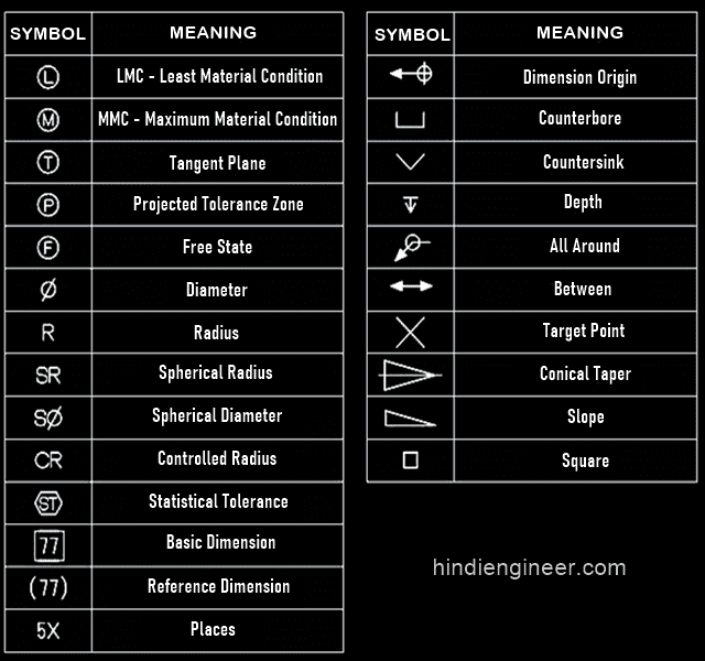
Symbol Of Engineering Drawing - Why abbreviations and symbols are needed for engineering drawing? Radius can be for the inside and outside curved surface on the part. Web basic types of symbols used in engineering drawings are countersink, counterbore, spotface, depth, radius, and diameter. You can also check out the gd&t symbols and terms on our site. How to read symbols in an engineering drawing? Web this chapter will introduce the five common categories of drawings. Icons and figures that represent common features like welds, tolerances, finishes, etc. Web just as an architectural drawing or blueprint shows you how to construct a building, an engineering drawing shows you how to manufacture a specific item or product. Web engineering drawings (aka blueprints, prints, drawings, mechanical drawings) are a rich and specific outline that shows all the information and requirements needed to manufacture an item or product. Usually, a number of drawings are necessary to completely specify even a simple component. This is especially true for the engineer. How to read symbols in an engineering drawing? Web the gsfc engineering drawing standards manual is the official source for the requirements and interpretations to be used in the development and presentation of engineering drawings and related documentation for the gsfc. Icons and figures that represent common features like welds, tolerances, finishes, etc. Web basic types of symbols used in engineering drawings are countersink, counterbore, spotface, depth, radius, and diameter. Web a convenient guide for geometric dimensioning and tolerancing (gd&t) symbols at your fingertips. This makes understanding the drawings simple with little to no personal interpretation possibilities. Web engineering drawings (also known as blueprints, prints, drawings, or mechanical drawings) are detailed outlines that represent the information and requirements required to build a certain item or product. Various symbols and abbreviations in engineering drawings give you information about the dimensions, design, and materials used. Web engineering drawing abbreviations and symbols in addition to traditional topics, it contains information on geometric dimensioning and tolerancing, design process and design for manufacturability, and the basics of descriptive geometry. Web in engineering drawings, symbols are graphical representations of specific features, instructions, or components. Alphanumeric characters used for labeling, numbering, and adding notes to the drawing. Work with runsom for your cnc programming projects. This is especially true for the engineer. Here are more commonly used engineering drawing symbols and design elements as below. Web symbols in mechanical drawings are graphical elements accepted by standards and codes. Web engineering drawings (aka blueprints, prints, drawings, mechanical drawings) are a rich and specific outline that shows all the information and requirements needed to manufacture an item or product. Web an engineering drawing is a type of technical drawing that is used to convey information about an. Here are more commonly used engineering drawing symbols and design elements as below. Alphanumeric characters used for labeling, numbering, and adding notes to the drawing. It is a graphical language communicating ideas and information. Web engineering drawing abbreviations and symbols are used to communicate and detail the characteristics of an engineering drawing. Various symbols and abbreviations in engineering drawings give. Web civil engineering calculators, steel data, checklists, standards lists, bend shape codes, construction calculator, symbols, units converter and much more in one app. Web engineering drawing employs a standardized set of symbols and notations: Why not just use a 3d model? Various symbols and abbreviations in engineering drawings give you information about the dimensions, design, and materials used. How to. It is more than simply a drawing, it is a graphical language that communicates ideas and information. We will treat “sketching” and “drawing” as one. This makes understanding the drawings simple with little to no personal interpretation possibilities. A common use is to specify the geometry necessary for the construction of a component and is called a detail drawing. One. Common engineering drawing abbreviations used in cnc machining. Why not just use a 3d model? Work with runsom for your cnc programming projects. Web an engineering drawing is a subcategory of technical drawings. The purpose of this guide is to give you the basics of engineering sketching and drawing. Here are more commonly used engineering drawing symbols and design elements as below. You can also check out the gd&t symbols and terms on our site. Web engineering drawings (aka blueprints, prints, drawings, mechanical drawings) are a rich and specific outline that shows all the information and requirements needed to manufacture an item or product. Alphanumeric characters used for labeling,. “sketching” generally means freehand drawing. It is a graphical language communicating ideas and information. It is more than a drawing; Web an engineering drawing is a subcategory of technical drawings. Key types of symbols are dimension symbols (representing measurements), feature symbols (surface roughness, contours, etc.), and material symbols (indicating the type of material used). “sketching” generally means freehand drawing. Click on the links below to learn more about each gd&t symbol or concept, and be sure to download the free wall chart for a quick reference when at. This application provides civil engineering tools and information on your fingertips.!! Web a convenient guide for geometric dimensioning and tolerancing (gd&t) symbols at your fingertips. Web. It is a graphical language communicating ideas and information. Web engineering drawings (aka blueprints, prints, drawings, mechanical drawings) are a rich and specific outline that shows all the information and requirements needed to manufacture an item or product. The purpose is to convey all the information necessary for manufacturing a product or a part. Key types of symbols are dimension. Web basic types of symbols used in engineering drawings are countersink, counterbore, spotface, depth, radius, and diameter. We will treat “sketching” and “drawing” as one. Web engineering drawing abbreviations and symbols engineering drawing abbreviations and symbols engineering drawing abbreviations and symbols Web engineering drawing abbreviations and symbols in addition to traditional topics, it contains information on geometric dimensioning and tolerancing, design process and design for manufacturability, and the basics of descriptive geometry. Web an engineering drawing is a type of technical drawing that is used to convey information about an object. Web engineering drawings (aka blueprints, prints, drawings, mechanical drawings) are a rich and specific outline that shows all the information and requirements needed to manufacture an item or product. Why abbreviations and symbols are needed for engineering drawing? Web how to read an engineering drawing symbol. Web the gsfc engineering drawing standards manual is the official source for the requirements and interpretations to be used in the development and presentation of engineering drawings and related documentation for the gsfc. Icons and figures that represent common features like welds, tolerances, finishes, etc. This list includes abbreviations common to the vocabulary of people who work with engineering drawings in the manufacture and inspection of parts and assemblies. Web basic types of symbols used in engineering drawings are countersink, counterbore, spotface, depth, radius, and diameter. Work with runsom for your cnc programming projects. Key types of symbols are dimension symbols (representing measurements), feature symbols (surface roughness, contours, etc.), and material symbols (indicating the type of material used). Web find common gd&t symbols in convenient charts broken down by their use in drawing and drafting. This makes understanding the drawings simple with little to no personal interpretation possibilities.
Engineering Drawing Symbols And Their Meanings Pdf at PaintingValley

Engineering Drawing Symbols And Their Meanings Pdf at PaintingValley

Mechanical Engineering Drawing Symbols Pdf Free Download at

Standard Engineering Drawing Symbols Design Talk
Engineering Drawing Symbols List Chart Explain Mechanical Drawing

Engineering Drawing Symbols And Their Meanings Pdf at PaintingValley

Engineering Drawing Symbols List Chart Explain Mechanical Drawing

Mechanical Engineering Drawing Symbols Pdf Free Download at

Engineering Drawing Symbols And Their Meanings Pdf at PaintingValley

Standard Engineering Drawing Symbols
We Offer You Our Tips Which We Believe Are Useful For Dispelling Uncertainty By Comparing The Symbol With Its Graphic Representation.
Radius Can Be For The Inside And Outside Curved Surface On The Part.
A) Civil Engineering Calculations 1.Cantilever Beam Stiffness Calculator 2.
“Sketching” Generally Means Freehand Drawing.
Related Post: